 Fault tree package
 RAM Simulator
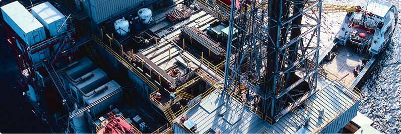
 Plasma - Oil and Gas
 Plasma - Wind (renewable)
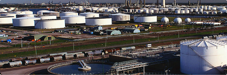
Supporting Our Clients Needs

Monaco Engineering Solutions
Risk & Safety Specialists
Powerful QRA & RAM Analysis Tools
About the Fault Tree Package
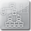
The Fault Tree (FT) module: involves the creation of a fault tree diagram composed of gates and basic events that represents the logical description of a system failure in terms of the failure of the components that comprise the system. The Fault Tree Module is a powerful systems reliability analysis tool that allows Fault Tree diagram analyses to be performed in an integrated environment. The Fault Tree Module is capable of analysing large and complex systems producing the full minimal cut set representation for identified systems and sub-systems.
Typical Fault Tree Diagram
Excel Output for the above Fault Tree
Event Id: This is the name or identification of the node.
Block Type: There are several block types used in the Fault Tree. These are either Basic Events or Gates (such as “AND” Gate, “OR” Gate or “Voting” Gate).
Node Category: There are several Node Categories defined in PLASMA;
- Failed House: This node category is used for events that are definitely not operating.
- Non-Critical: As the name suggests, these nodes do not affect production and they can be placed anywhere in the system as long as they are not connected to critical nodes/RBDs.
- Revealed (Steady State): By default all nodes that are connected to a source are critical and would affect production when they fail. In order to make a node non- critical, it has to be disconnected first and then its category changed to Non- Critical.
- Standby: This category is used for systems in the stand-by mode. Stand-by systems are an intermediate case between revealed and un-revealed failures. In the stand-by mode the failures are un-revealed, whilst in the operating mode they are revealed.
- Un-revealed (Dormant): This node category refers to failures that will remain un-revealed until an inspection takes place. They are used to represent failure of components which are not in continuous use and whose failures are not revealed until inspected or called into use.
- Working House: This node category is used for events that are definitely operating.
Failure Rate: The number of failures of an item per unit time;
Active Repair Time: Average time required to analyse the failure, repair and return the item to a state of readiness;
Coverage Factor: 0% Coverage in refers to all failures being dangerous and all un-revealed;
Test Interval: This refers to periodic testing of systems that are not in continuous operation (see dormant node category).
Unavailability: This is the Probability of Failure on Demand (in the case of dormant failures). This term is used to quantify loss of safety due to random hardware failures. This parameter includes the contribution from both revealed and un-revealed failures.
Integrity Level: Discrete level (one out of four) for specifying the safety integrity requirements of the safety function(s) to be allocated to the safety related systems, where SIL 4 has the highest level of safety and SIL 1 the lowest.
- IL 1 - PFD = 0.1 to 0.01;
- IL 2 - PFD = 0.01 to 0.001;
- IL 3 – PFD = 0.001 to 0.0001; and
- IL 4 – PFD = 0.0001 to 0.00001.
Minimum Cut-Set: It is defined as the smallest combination of primary failures which, if they occur, will cause the top event to occur.